The Gigapixel Camera #1 (GPC1), which uses 60 Orthogonal Transfer Arrays devices, is mounted in the focal plane of the PS1 telescope. It has a field-of-view of about 7 square degrees, with a pixel scale of 0.258 "/pixel.
The Gigapixel Camera #1 (GPC1) uses Orthogonal Transfer Arrays devices, a concept developed by Tonry et al. (1997). The detectors in GPC1 are CCID58 back-illuminated Orthogonal Transfer Arrays (OTAs), manufactured by Lincoln Laboratory (Tonry et al. 2006, 2008). They have a novel pixel structure with 4 parallel phases per pixel (Tonry et al. 2008) and required the development of a new type of controller (Onaka et al. 2008). GPC1 is actually populated with two different kinds of CCID58s, the CCID58a with a three phase serial register, and the CCID58b which has a two phase serial register (Onaka et al. 2012). For the science data discussed in the PS1 papers and presented in the public data release, the devices were always operated without OT and in a normal readout mode, and none of public PS1 data has OT correction. The detectors are read out using a StarGrasp CCD controller, with a readout time of 8 seconds for a full unbinned image. Performance assessments are presented in Tonry et al. (2008); Onaka et al. (2012)
The focal plane of PS1 comprises a total of 60 CCID58 OTA devices Tonry et al. (2008). Each of these devices consists of an 8 × 8 array of individual addressable CCDs called “cells”. The overall format of a single OTA is a 4846×4868 pixel array with a pixel size of 10μm which subtends 0.258 arcsec. Each OTA device is made up of 64 cells where each cell is 590×598 pixels. The cells are separated by a gap between columns, that is 18 “inactive” pixels in size, and a gap between rows that is 12 inactive pixels in size. Thus a single OTA device contains a single piece of silicon with 64 cells in an 8×8 array separated by a grid of 7×7 internal streets. Further more, there is physical gap between the devices as mounted in GPC1. The separation between the OTA devices is 1400 microns (approximately 36 arcsec) in the x direction and 2800 microns ( approximately 70 arcsec) in the y-direction. In practice the devices are not perfectly spaced and can have some small rotation with respect to one another.
 |
|---|
| Fig 3 from Chambers et al. 2016. Gigapixel Camera 1 focal plane layout and mask. The non-functioning cells are blanked out in white. |
The telescope, detector devices, and control electronics each contribute a variety of artifacts to the GPC1 images. Where possible these artifacts are identified and the pixels are masked or modified during processing and flags are set in the database. These include optical ghosts from reflections in the optics, glints from scattered moon light, glints from structure in the camera, regions of poor charge transfer in the devices, persistence or “sticky charge” from saturation leaving “burn-trails” that persist for all successive images for tens of minutes, electronic ghosts from cross-talk in the electronics, and correlated read noise from the fiberflex that transmit the signal through the cryostat wall. These are identified and masked where possible in the detrending procedure as part of the chip processing stage in the IPP. There is a detailed discussion of the defects and how they are masked in Waters et al. (2017). These defects are visible on the focal plane in the single exposure frames, but the stacked images made from the multiple images taken over the survey duration are composed of dithered frames.
If we take the sky area covered by the GPC1 footprint to be the area of the inner blue circle in Figure 3 (7 sq degrees) then the dead cells, pixel gaps and masking of defective pixels account for an overall loss of 20% of the focal plane in any one exposure. There is an additional dynamic masking of around 2-3% per exposure, which mostly covers the “burn-trails”. Therefore the overall fill factor of the camera is 76 ±1% per exposure and this is mitigated by the dither and stack techniques that were employed in the 3π and Medium Deep Surveys. The first data release (DR1) from the STScI MAST archive is the stack images only and hence the images will mostly look continuous, although there are areas where a combination of poor devices and fewer than 12 exposures mean masked regions creep through to the final product
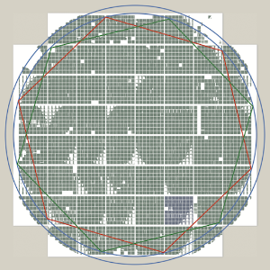
Fig 3 from Chambers et al. 2016. Gigapixel Camera 1 focal plane layout and mask. The non-functioning cells are blanked out in white.