Page History
...
Consider a very short, fixed time interval δt = 0.1 seconds during which the location of the slit may be considered to be fixed in the sky. (The interval at which FIMS_TIME was measured, 0.1 seconds, was adopted for this time step δt.)
During the time interval δt, all points (e.g., A,B,C,... in Figure 1) in the field of view (FOV) will have the same exposure time δt.
Panel borderColor #00617E bgColor #E3EEF1 borderStyle solid 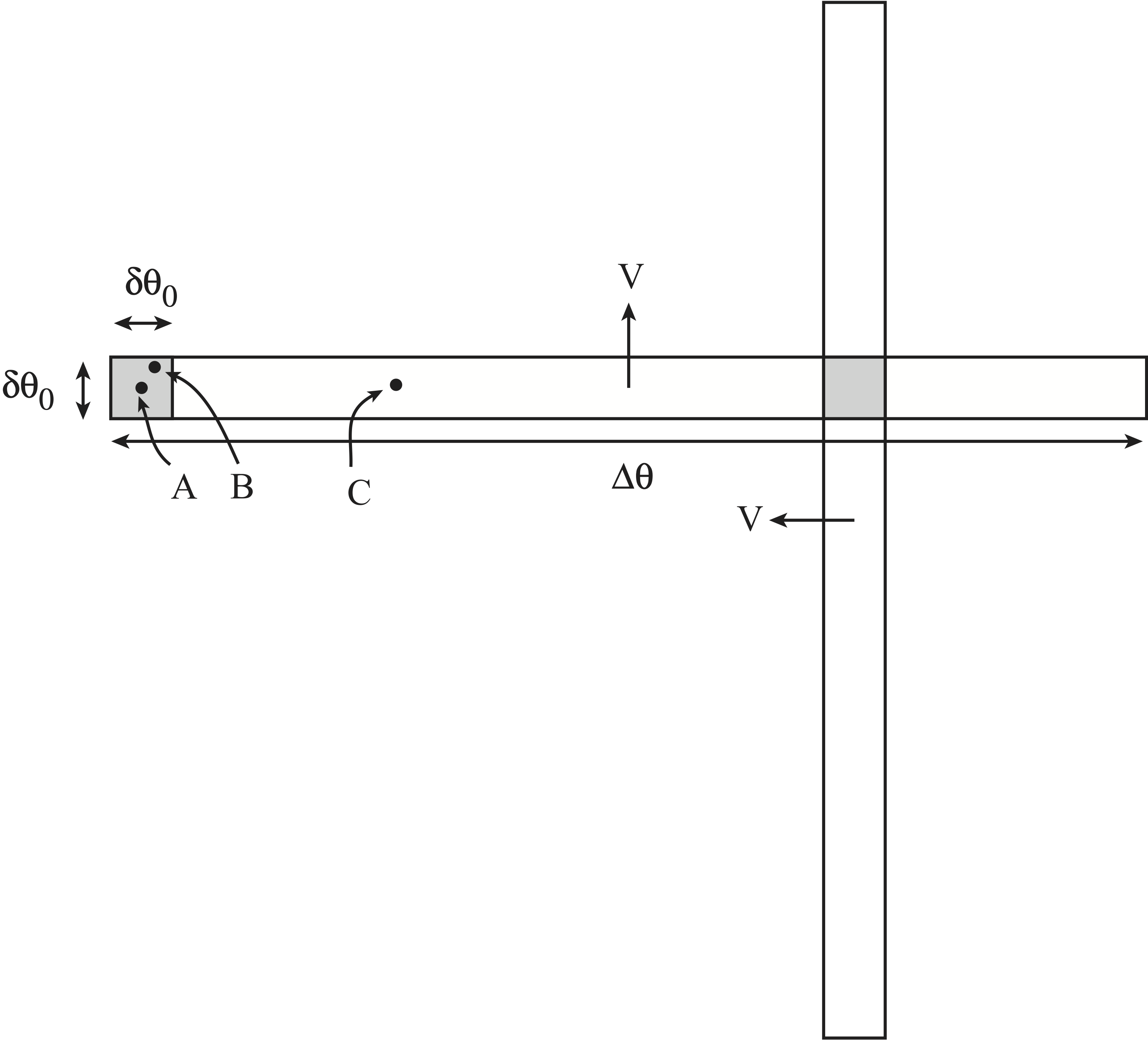
Figure 1: Schematic diagram to calculate exposure time. Here, δθ0 is the slit angular width and ∆θ is the view angle perpendicular to the slit’s long axis. V is the drift angular velocity of the FOV.
δt = 0.1 seconds later, the FOV center now points to a new position on the sky. This position is different from the center of the first FOV, but still overlaps with the first FOV. The region of overlap between the two FOVs now has an exposure time 2δt.
...