This article describes the design and manufacturing of the FIMS-SPEAR instrument.
On this page...
The FIMS-SPEAR instrument consists of dual imaging spectrographs optimized for the detection of faint diffuse far-ultraviolet (FUV) radiation. The overall FIMS-SPEAR design was derived in part from an earlier instrument, the Extreme Ultraviolet Spectrograph for the Observation of Diffuse Radiation (EURD, from the original Spanish acronym). The FIMS team was responsible for the development, manufacturing, and operation of the optomechanical and electronic systems, while the SPEAR team was responsible for overall system design and the development and manufacturing of the microchannel plate detectors.
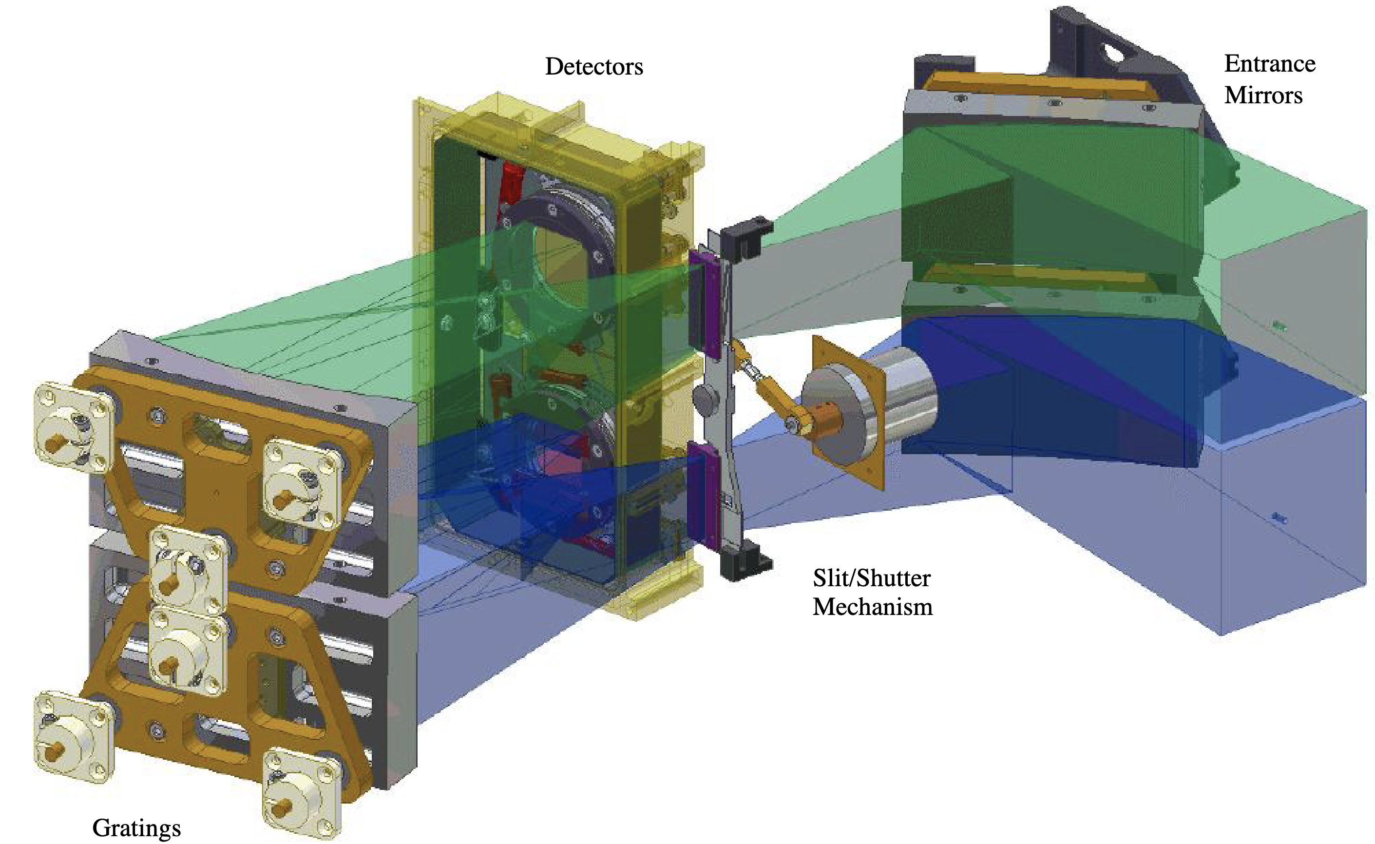
Schematic view of the FIMS-SPEAR optical path from Korpela et al. 2003, SPIE, 4854, 665, re-printed with the permission of the publisher (SPIE) and first author (E. Korpela). See below for full reference and author list.
Spectral Channels
The two spectral channels are as the short-wavelength S-band (λλ 900 – 1175 Å) and the long-wavelength L-band (λλ 1335 – 1750 Å), with a spectral resolving power of about λ/Δλ=550 in both bands. The bands were chosen to include astrophysically-important emission lines from abundant ionic species while avoiding contamination by the intense H I λ1216Å and O I λ1304Å geocoronal lines. Each channel consists of a collecting mirror feeding a shutter-slit unit, a diffraction grating, and a detector. Each channel uses identically configured 5x8 cm2 elements in the same geometric configuration and shares the same slit and detector focal plane.
Optical system
The two-element f/2.2 optical system has an off-axis parabolic-cylinder collecting mirror that focuses plane-parallel light to a slit. Cylindrical radiation from the slit then strikes a constant-ruled grating with an elliptical figure that corrects on-axis aberrations to the third order. Diffracted light is imaged as a spectrum on a planar position sensitive photon counting detector. Radiation from off-plane angles is imaged along the detector perpendicular to the dispersion plane, analogous to a slit-imaging spectrograph. The cylindrical-source scheme doubles the usable imaging angle in comparison with classical point-source spectrographs, a determining factor for diffuse source sensitivity.
Diffuse FUV spectrograph performance is a function of optical quality, dispersion, efficiency, and scattering due to surface or grating imperfections. The collecting mirrors were measured to have a focal line width of < 100 μm FWHM at the focal distance of 15 cm and a surface roughness of 10 Å RMS. The gratings were polished to < 35 Å RMS surface roughness and holographically ruled with a blazed profile formed by ion-beam ablation of chemically etched grooves, providing 65% peak groove diffraction efficiency. The L-band and S-band channels use the same grating figure, but the L-band channel works in first order at 3000 line mm−1 and the S-band channel works in second order at 2250 line mm−1. The L-band and S-band optics use coatings, MgF2 on Al and B4C on a thin Cr base, chosen to optimize bandpass efficiency and resist degradation by atomic oxygen.
The instrument’s optical resolution was designed to deliver 2 to 7 arcmin imaging, depending on the imaging angle. Combined with a pointing knowledge of about 5 arcmin, this yielded a spatial resolution of 5 to 10 arcmin on-sky.
Detectors
Each channel's spectrum is focused upon a separate position-sensitive photon-counting microchannel plate (MCP) stack. The MCPs are coated with a CsI and KBr photocathodes. The stacks share a single position-sensitive read-out and electronics system to conserve spacecraft resources. The unique detector read-out uses a cross delay line anode system with one bifurcated delay line that senses both channel stacks. The axes of the anode are rotated 15 deg with respect to the dispersion axis, to mitigate the appearance of false spectral features due to anode or electronics differential non-linearity.
A stimulation unit injects artificial event signals at the field corners so that thermal drifts in the position encoding system can be calibrated in flight. The amplifiers also produce a signal proportional to each event's charge amplitude to allow the rejection of low amplitude noise or high amplitude ion and cosmic ray events. Low-amplitude noise events are discarded by the on-board electronics. A count-rate monitor turns off the detector in case of excessive count-rates. Observation restart is automatically attempted within 2 to 30 s so that entire survey sweeps will not be lost while momentary bright stars transit.
S-band detector sensitivity
In the final thermal vacuum test of the FIMS-SPEAR flight model, one of the two MCP detectors malfunctioned. The detector could not be restored to its normal state, so the sensitivity in the S-band channel became severely lowered. In-flight calibrations were used to characterize this sensitivity loss. Due to the low and variable sensitivity, caution should be exercised in interpreting S-Band data.
Coatings
Care was taken to reduce background noise from strong airglow lines, stars, detector and ion background, and optics fluorescence. The L-band channel includes a flexure-mounted, zero-power CaF2 cylindrical meniscus filter that excludes geocoronal Lyman α before the 150 μm slit. The L-band response is limited at short wavelengths by the CaF2 filter and at long wavelengths by the detector photocathode such that high-order diffraction is rejected. The S-band is unfiltered and its response is limited by falling optical coating and diffraction efficiency at short wavelengths, and by the detector photocathode at long wavelengths, although high-order response to the bright He I λ537Å was found in flight data. The S-band channel uses MgF2 windows that transmit λ >1150 ̊A to detector areas adjacent to the science field so that instrumentally scattered Lyman α airglow can be monitored. Consequently, the science fields of view (FOVs) are 7.4° x 4.3’ in L-band and 4.0° x 4.6’ in S-band.
Shutter modes
The slit shutter aperture can be set to admit 0%, 1%, 10%, or 100% of the available light for safe and photometric observations of bright sources.
Recommended external documentation
In approximate order of priority for the general user:
- Korpela et al. 2003, SPIE, 4854, 665.* A more detailed description of the optical design, detectors and detector electronics, payload control, power distribution, housekeeping, data handling electronics, and on-board software.
A full-text re-print of Korpela et al. 2003 is made available here with the permission of the publisher (SPIE) and first author (E. Korpela).
Eric J. Korpela, Jerry Edelstein, Peter Berg, Mark Shane Bowen, Raymond Chung, Michael Feuerstein, Wonyong Han, Jeffrey S. Hull, Ho Jin, Dae-hee Lee, Kyung-wook Min, Uk-won Nam, Kaori Nishikida, Jin-geun Rhee, Kwangsun Ryu, Kwangil Seon, Barry Y. Welsh, Insoo Yuk, "The SPEAR science payload," Proc. SPIE 4854, Future EUV/UV and Visible Space Astrophysics Missions and Instrumentation, (24 February 2003); https://doi.org/10.1117/12.459970.
- Edelstein et al. 2006, ApJ, 644, 159. See Section 2 for a broad overview of the instrument design. (Note: Section 3 onwards contains information on ground-based data processing that may not apply to all current products.)
- Ryu et al. 2003, SPIE, 4854, 457.* Detailed description of the optical system's development, including the mirrors and diffraction gratings.
- Kwak & Park 2004, JASS, 21, 109.† Detailed description of process through which photon arrival times are recorded, which is critical for the determination of photon sky positions. See Data Processing in MAST's manual for serious issues that arose regarding time synchronization.
- Rhee et al. 2007, NIMPA, 575, 527 and Nam et al. 2003, SPIE, 4854, 602*. Detailed descriptions of the MCP detector electronics.
- Seon et al. 2004, PKAS, 19, 65.† Optical design theory background for FIMS-SPEAR, with general applications for designing imaging spectrographs optimized for diffuse emission.
*Written before launch, while manufacturing and testing were still taking place.
†Currently available only in Korean, with English abstract/tables/figures.
Supplementary external documentation
In alphabetical order:
- Bowyer et al. 1997, ApJ, 485, 523. Description of the EURD instrument, a predecessor which inspired aspects of FIMS-SPEAR's design.
- Edelstein et al. 1999, ASPC, 164, 307. Early concept for a FIMS-SPEAR-like instrument.
- Nam et al. 2002, JASS, 19, 273.*† Performance testing of the detector electronics system.
- Park et al. 2001, JASS, 18, 209.*† Exposure map predictions and early notes on operational scheduling.
- Rhee et al. 2002, JASS, 19, 57.*† Design of MCP detectors / fabrication and testing of the delay line readout electronic system.
- Ryu et al. 1998, JASS, 15, 359.*† Early optical designs and performance predictions for a FIMS-SPEAR-like instrument.
- Ryu et al. 2000, SPIE, 4231, 312.* Testing method of off-axis parabolic cylinder mirror.
- Ryu et al. 2000, JASS, 17, 67.*† Optical tolerance analysis for FIMS-SPEAR.
- Ryu et al. 2001, JASS, 18, 239.*† Manufacturing and testing of the off-axis parabolic cylinder mirror.
- Seon et al. 2000, JASS, 17, 240* and Han et al. 2001, ASPC, 246, 113*. Brief reports from early in mission development.
- Seon et al. 2000, OEF 137.* Optical tolerance analyses and tables describing properties of the optical system.
- Seon et al. 2000, JASS, 17, 77.*† Detection simulations for O VI emission.
- Seon et al. 2001, JASS 18, 81.*† Thermal and structural testing of the grating.
- Seon et al. 2001, JASS, 18, 219.*† Optical performance simulations / sensitivity and error budget analysis.
- Seon et al. 2002, JASS, 19, 283.*† Thermal analysis of the electronic board.
- Seon et al. 2003, J. Korean Phys. Soc. 43(4), 565.* Detectability test of H2 Lyman-Werner band emission.
- Yuk et al. 2003, PKAS, 18(1), 87–95.† Description of the optical system's baffles.
*Written before launch, while manufacturing and testing were still taking place.
†Currently available only in Korean, with English abstract/tables/figures.